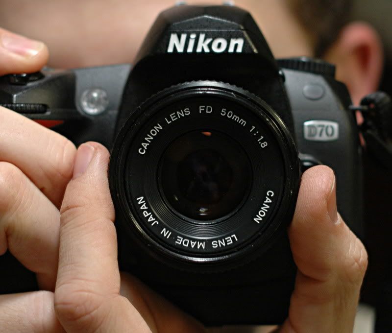
This article is to show you what I did to allow me to mount my 50mm f/1.8 "new" FD mount Canon lens to my F mount Nikon cameras. This is how I did it. Your experience may vary.
I have been inside the "old" FD mount version of this same lens. It is WAY different. The concept is the same but the instructions on this page do NOT apply if your lens has a silver mounting ring.
Caveats up front:- It will not focus to infinity unless you shave the mirror in your camera. There are smashingly-good lenses made by Nikon (and other makers) to fit your Nikon, available for $100 new at retail - shaving the mirror is not worth it, to me.
- The aperture stop-down lever works the wrong way, so you can only have manual stop-down of the iris, and NO automatic iris control happens inside the camera.
- It is only (duh?) has manual focus
- Manual aperture control. There is no exposure metering of any sort, so exposures will have to be done the new way by chimping each exposure or the old way with tables and light meters.
- This conversion, done all the way, renders the lens incompatible with your Canon SLR.
That said, this conversion cost me about $10 and I didn't have a fast prime lens of any sort at the time, so this was worth the effort involved. To be quite clear: I would not do this if I had the hundred bucks to buy a new lens with autofocus and automatic metering. Well, maybe I would, but I would shoot the Nikon glass and have this for a conversation piece!
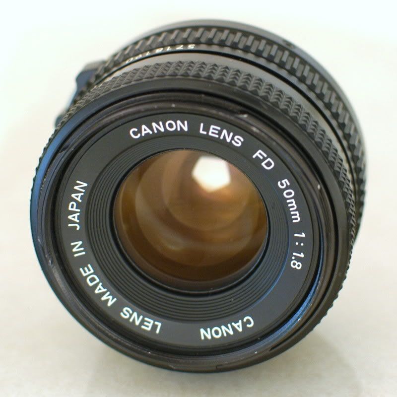
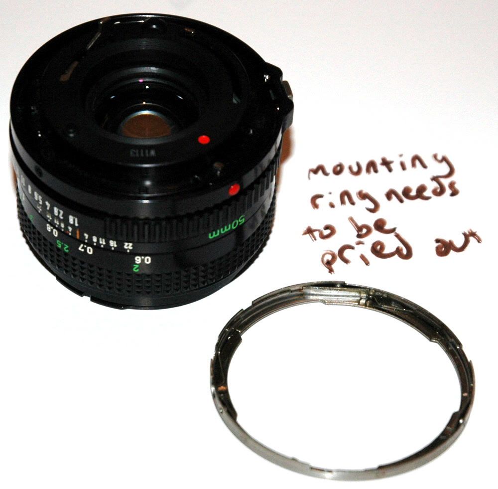
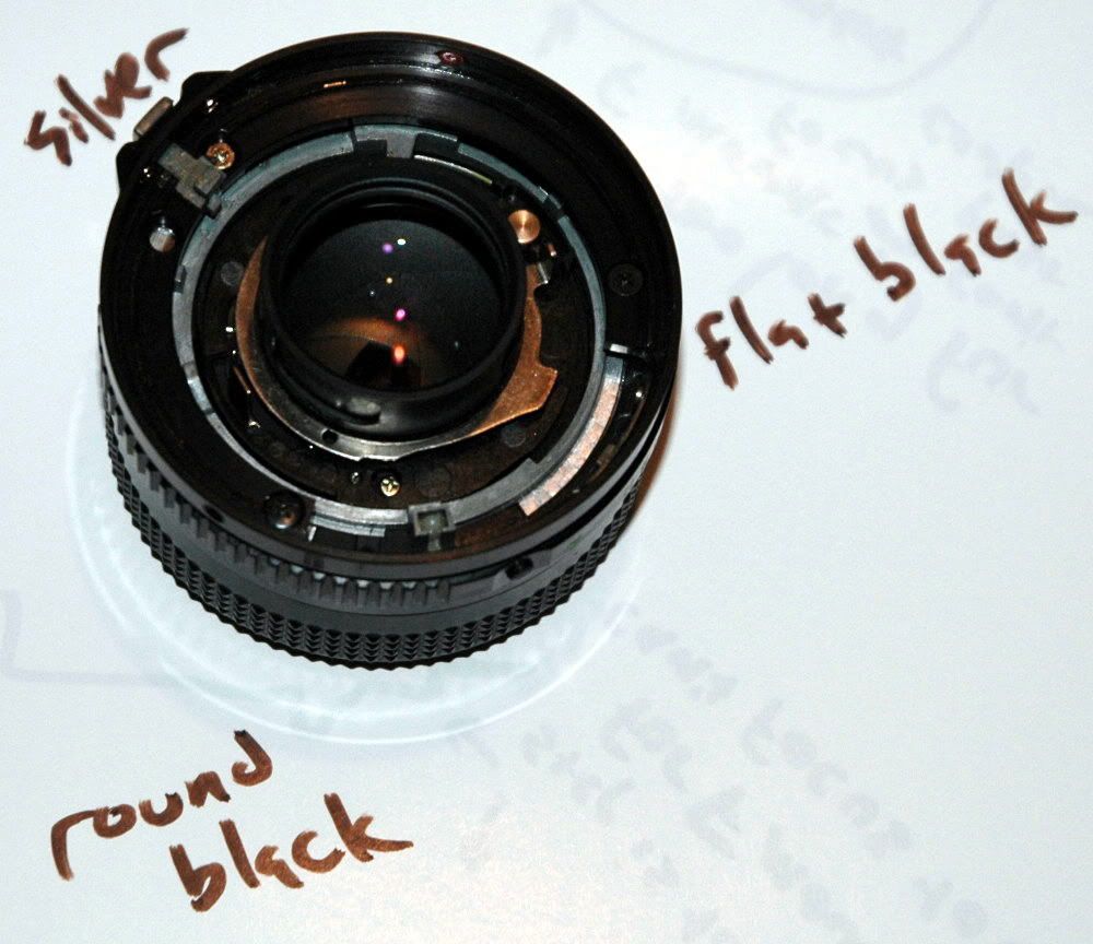
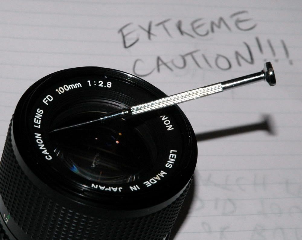
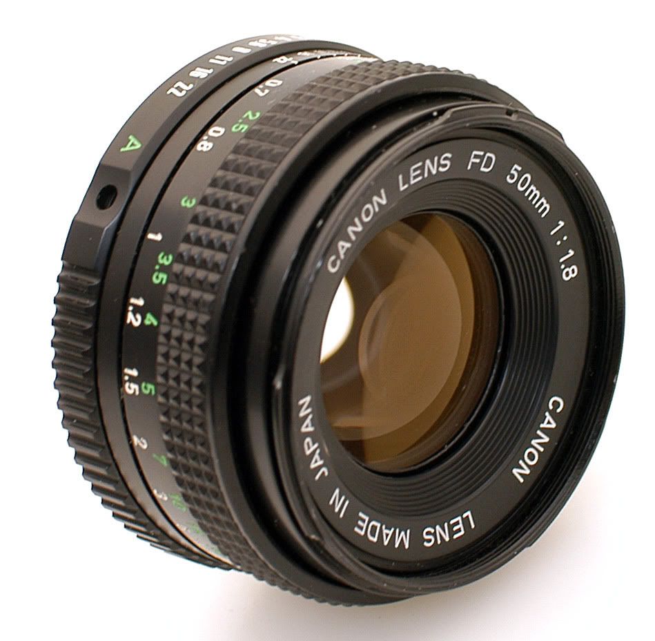
The victim: a very nice example of the once-standard Canon lens. If you had a Canon you had one of these. Now you have it on a shelf in the basement. If you get $40 for one in this condition on eBay, you are doing well. They often go for much less.
 Click on any image to see it at much higher resolution.
I handheld this on the front of my camera to get an idea of whether it was even worth trying. I picked a random item nearby as a subject.
First, with my general purpose zoom lens, with the aperture as wide-open as it will go (f/3.5 at 35mm).
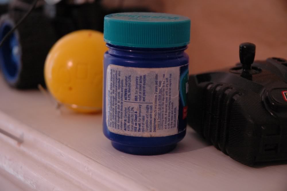
Then, with this Canon lens (50mm f/1.8)

Sharp focus on the subject, background defocused and then some. This convinced me the project was at least worth a try. The automatic lens shot at 1/20 second and the manual lens got the same exposure at 1/30 second - 50% faster is a nice bonus.
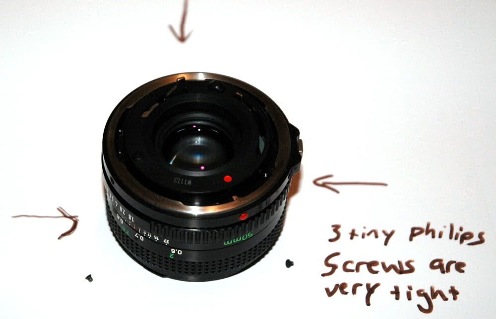
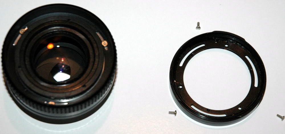
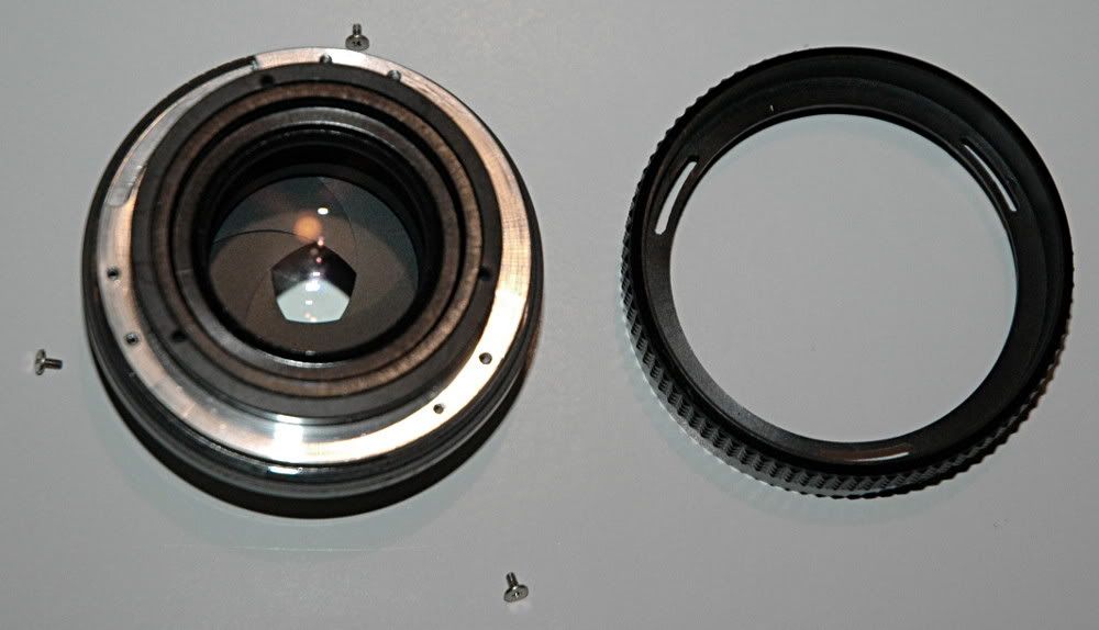
Creative destruction, here we go! Three tiny philips screws hold the mount ring in place. They are ridiculously tight. An old, worn screwdriver will strip these out and ruin your whole day.
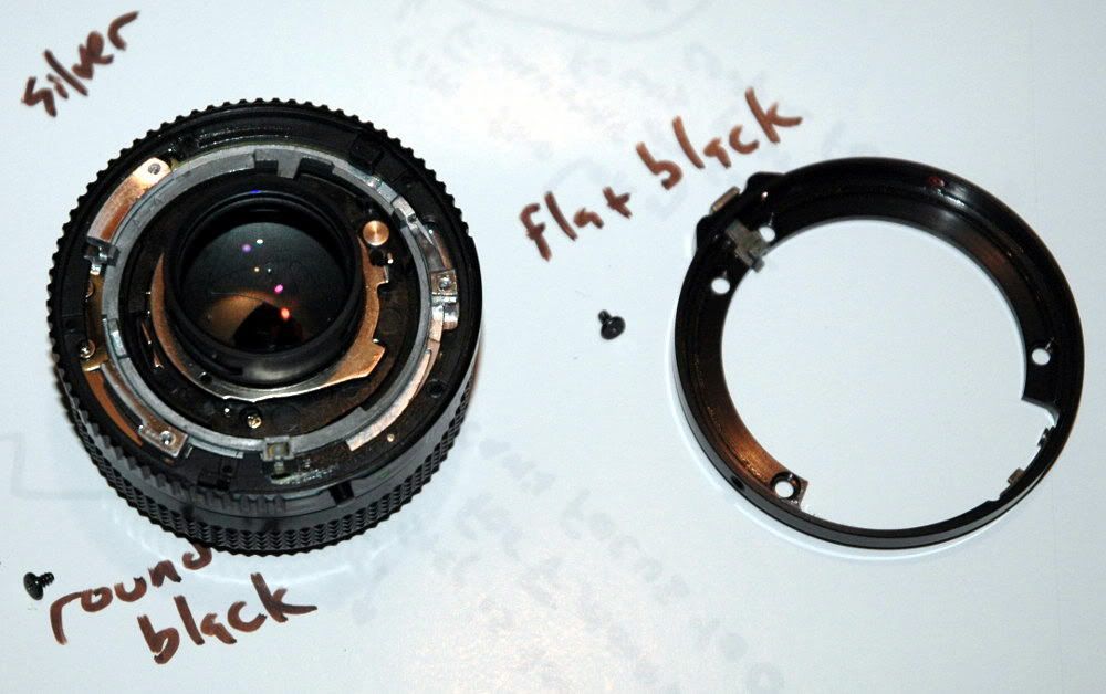
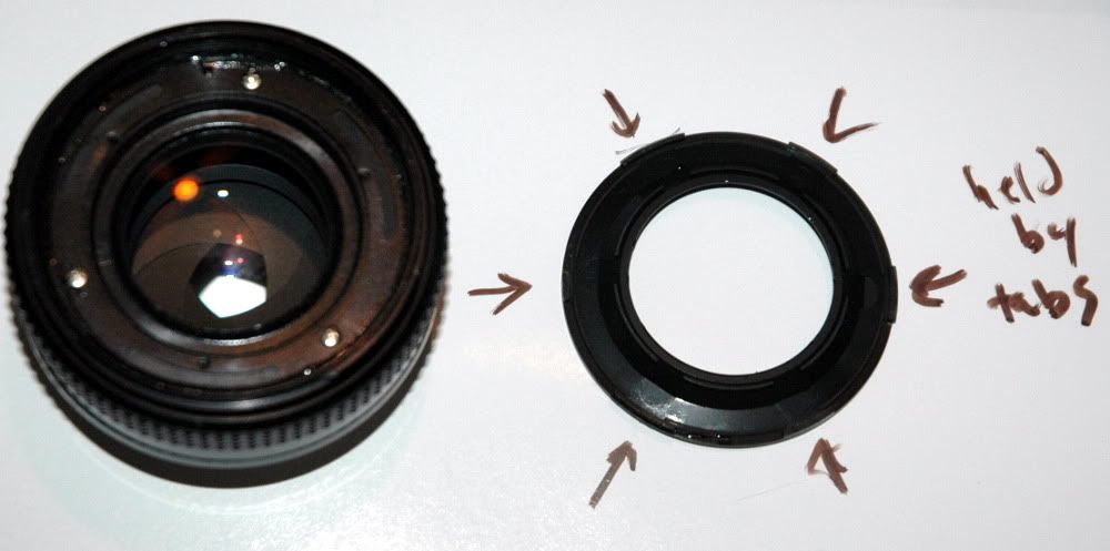
The metal mounting ring lifts out, with slight resistance
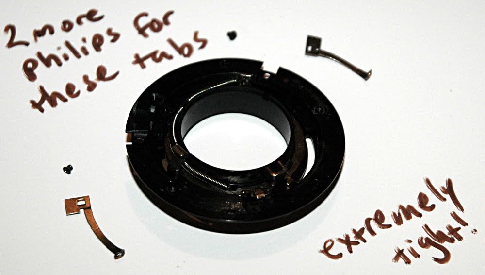
Here are two little metal tabs that have something to do with proper mounting on a Canon SLR. They make reassembling the lens a hassle and I was going to be reassembling this one several times. To make disassembly/reassembly easier, I just pulled these off. They use the same little baby philips screws, so when you throw these tabs away you will have two spare screws if you stripped out the mounting ring screws.
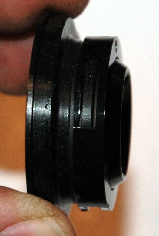
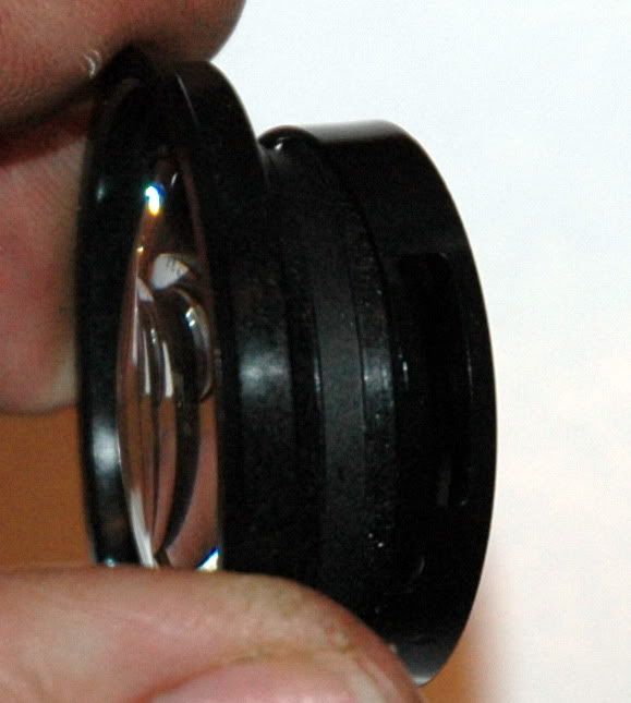
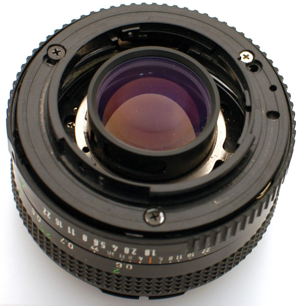
Right off the bat, I can see there is going to be difficulty. The whole back of the lens assembly protrudes, and the protrusion is too wide to fit physically inside the Nikon F mount. This thing has got to go.
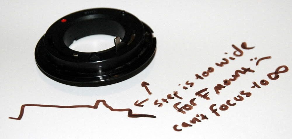
The Canon FD lens mount specification has a flange to focal plane distance of 42mm. The Nikon F mount has an FFD of 46.5mm. What this means is that this Canon lens has to be physically inside a Nikon camera to focus properly. The Nikon lens mount flange on the body is too narrow to admit the back of the lens if you "only" remove the Canon FD mounting hardware.
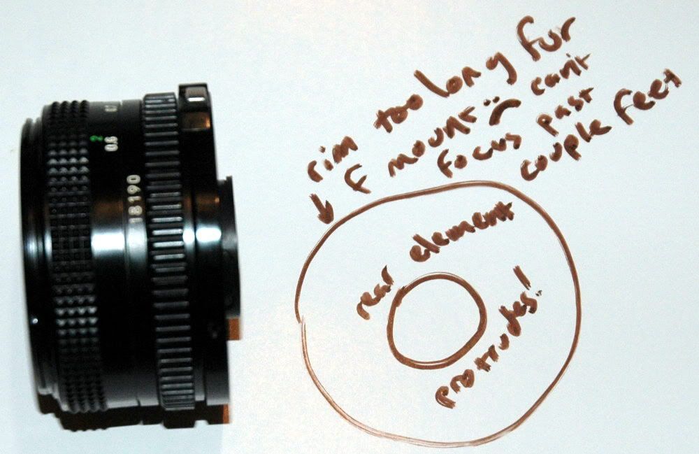
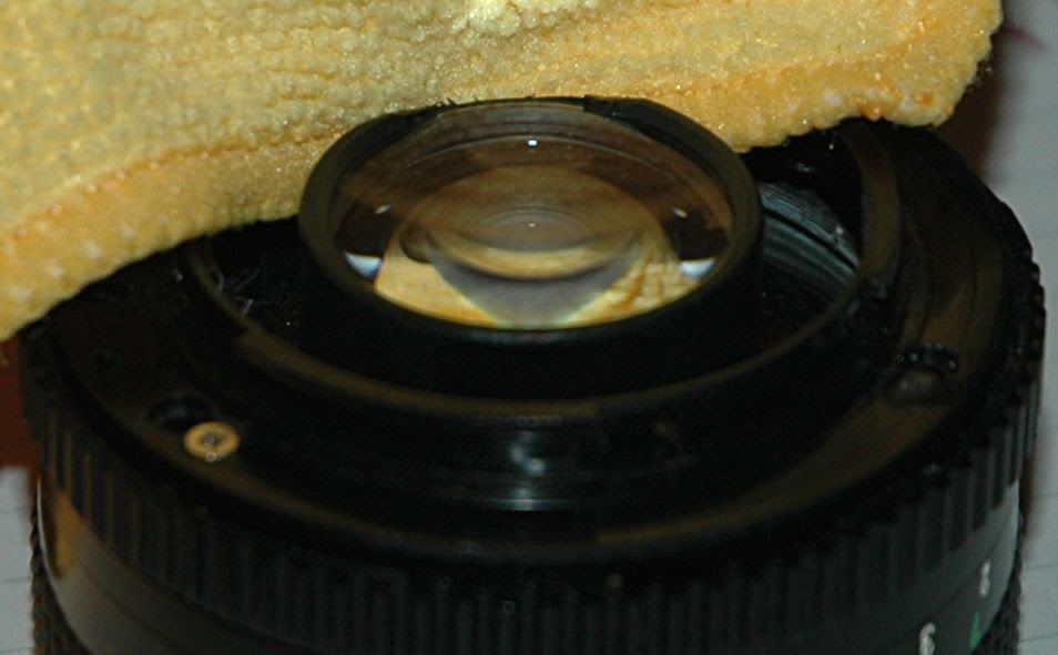
More problems come up immediately! The rear element is now protruding a bit, which gives me the willies thinking about the mirror in my camera. That, plus the optics are too far away. I held the lens up to the camera like this, and found it will only focus as far away as a couple of feet. Not great.
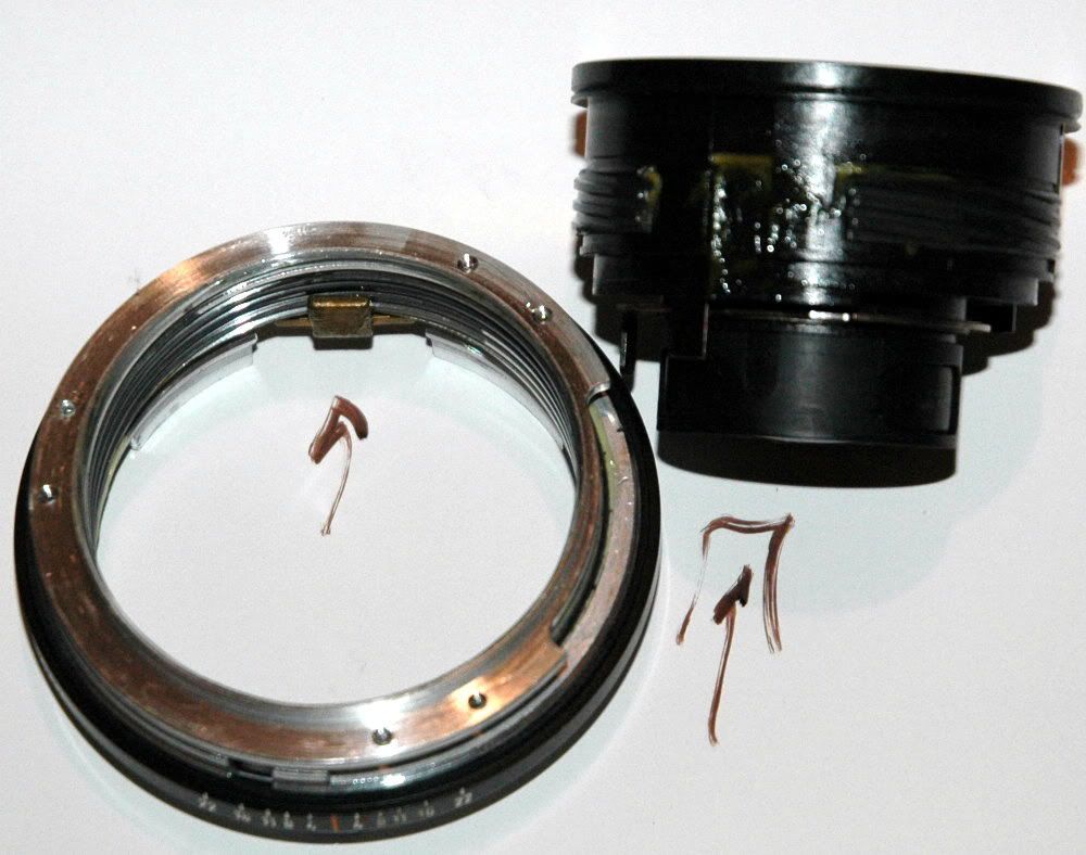
Three screws hold this ring on. They are all different. Make a note of where they came from so they can go back there during reassembly. Be VERY CAREFUL not to lose these particular screws, and don't mix them up. They are not the same thread pitch, and you will need to use them to hold on your F mount in a little while.
The three screws go in three protrusions coming off the lens chassis. These are the attaching points for the F mount we will install.
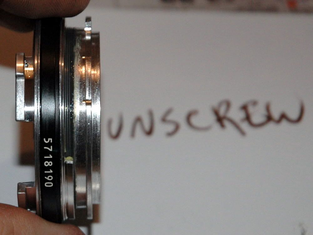
After that ring is removed, we find that this big clunky-looking plain metal ring falls out with no resistance. At a wide aperture setting, the aperture ring also falls out.
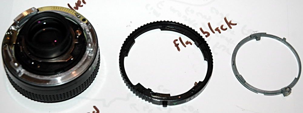
Another thing which may or may not fall out is the aperture f/stop clicker. This lives inside the aperture ring, and is a little cylinder of metal, lightly springloaded. The grooves on the off-white plastic piece are the f/ stop clicks. The grease in the little hole where the clicker lives holds the spring and cylinder in with surface tension/gooiness - they are not retained at all. I lost this little cylinder when it went flying out of
my 100mm FD project lens. It will stay lost, so be careful of this part if you like clicky f/stop settings.
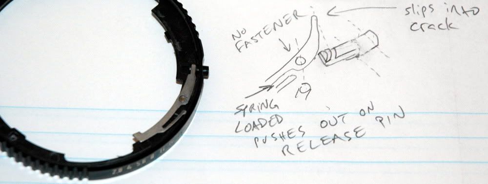
Another feature of the aperture ring is this little metal lever/tab assembly. It is part of the stop mechanism. Setting the lens to "A" on your Canon SLR was done with this button, pushing this lever inside.
The lever is not retained, and will want to fall off.The little thin section of the arm is an effective spring. Pull the lever out, and the plastic button is free also. The mounting/pivot pin holding the lever pulls right out.
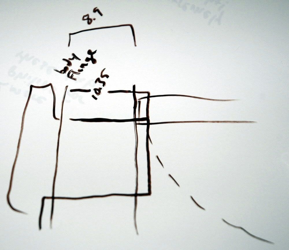
Now we can see just how much of a problem is the protrusion of the rear lens element. Taking a picture inside a camera is a bit of a problem for me, so I had to break out the calipers and I figure this is what it would look like with MSPaint X-Ray vision. It turns out that you have about 1.4mm too much lens to get this thing to sit properly to be able to focus to infinity. Stated differently, you would need to shave 1.5mm to 2mm from the middle of your mirror to use this lens to its full potential. That's on a DX camera. For a 35mm film or FX digital body, I believe this would be an even bigger problem.
Well, that was a bummer. Okay, on to the front of the lens. Some other lenses have their trim rings screwed into the filter mounting threads, and you have to use a cork or rubber stopper of the appropriate diameter to remove the ring. This lens trim ring is NOT screwed in. It is held in by tabs inside.
This is the same setup as is used on the FD 100mm f/2.8. I didn't get a picture of this process on the 50mm, so just pretend this is a picture of the 50 and keep going. Use a SMALL flat screwdriver or other pokey thing. Some people recommend a wooden implement to avoid damaging the front lens. You might want to use a pad like a bit of cloth or tissue or something. Just be careful. You don't actually HAVE to touch the lens to pry out the trim ring.
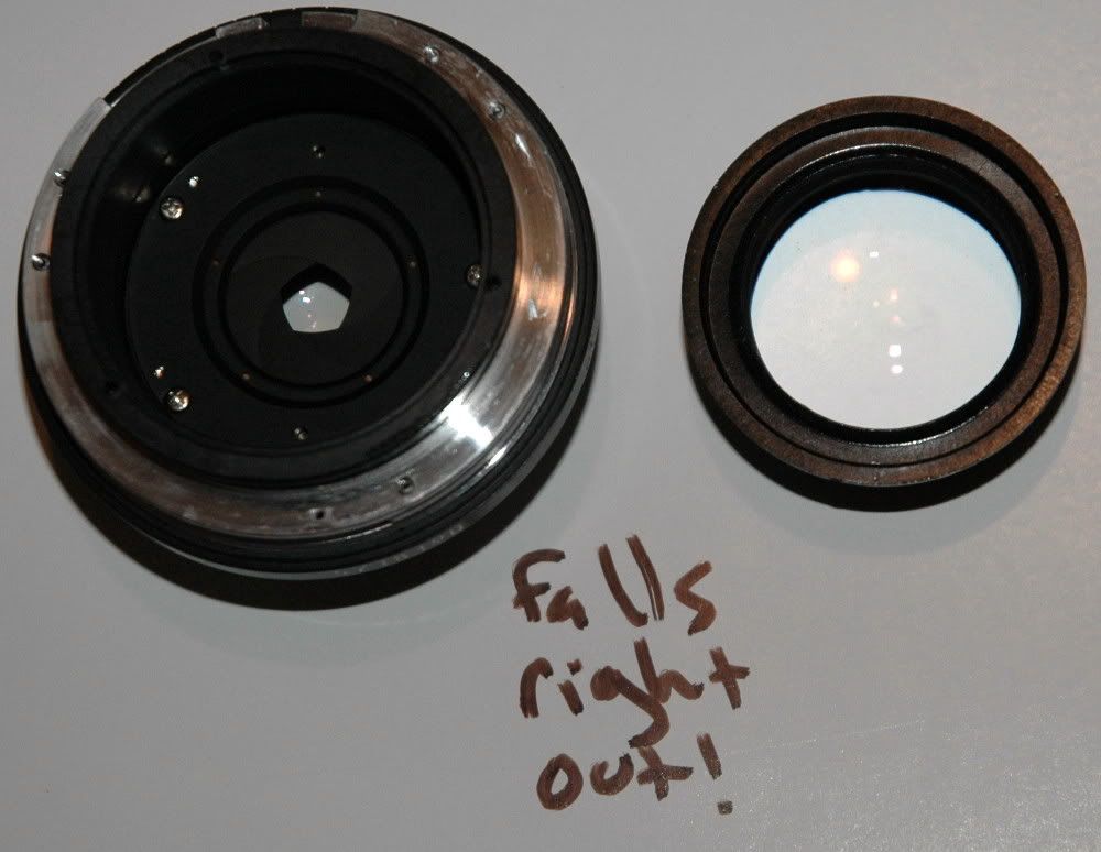
Behind that trim ring, we find more screws. Pull them. This is the retainer for the front lens group. Removing it allows the front lens group assembly to fall out in your hand. Or on the floor, or in the dirt, or wherever. Be careful to set it gently to the side instead of dropping it.
Side view of the front group. Stand it on its side, or set it on its back on a clean microfiber cloth.
More screws, pull them also. This is the focus ring.
Now is the time to scribe or magic marker a line all the way down the side so you can see where the focus helicoids were lined up. I didn't, but I recommend you do because the next bit took an unnecessarily long time without any sort of a reference line.
The lens carrier assembly will unscrew and then push out of the mount. The tab (left) has a corresponding slot (right) on the lens carrier.
The threads on the helicoids will go together in several different orientations. Without a reference line, you will end up with random alignment and need to reassemble it again and again if you disassemble the helicoids. Note there are TWO sets of helicoid threads with dramatically different thread pitches. Turning the focus ring moves two parts of the lens at different rates. This is magic . . . and very easy to get lined up the wrong way. I STRONGLY RECOMMEND not fooling with this and just leaving the focus helicoids together if you are just in here to see what it looks like. I buffaloed right in there and then said "uh-oh . . . " but you can't do this mount conversion without re-orienting the helicoids.
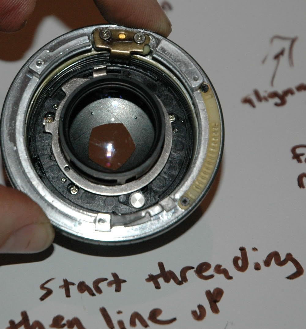
You want to adjust the focus mechanism of the lens so you can have more than a few feet of useful range. Unscrew the fine-pitch metal helicoid and back it up one set of threads. Start it threading it in again. Start to screw the plastic helicoid in again. Line up the tab/slot, and gently proceed to screw it all together.
The bronze thing at 12:00 in this picture is the tab. It lives in a slot on the plastic lens carrier. It makes the lenses move in/out instead of allowing them to rotate. If you don't get this tab in its slot, the whole mechanism will lock up when you try to screw it together. This
will happen to you. Do not force anything. Wiggle it apart carefully when it gets stuck and try again. Have I mentioned that this took me a while?
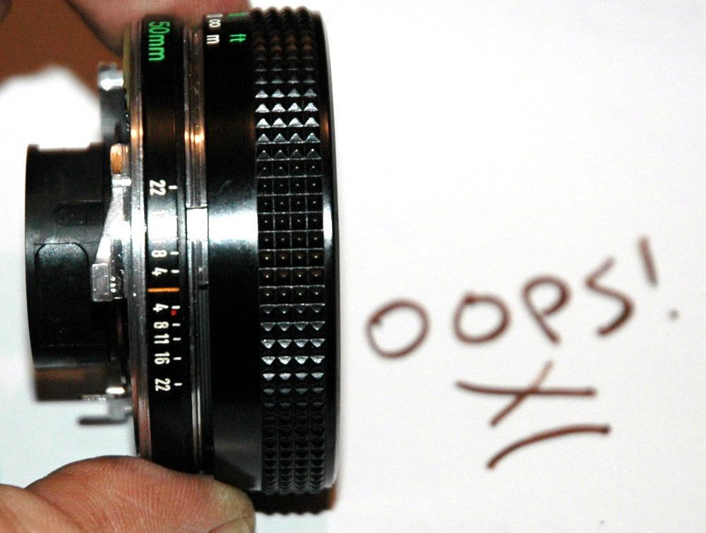
I backed the focus helicoid out too far and/or didn't get the alignment right. I ended up with a big gap between the focus ring and the lens chassis. Boo! If you see this, you might have something closer to a macro lens, but you can't have focus past a few feet. I wanted infinity focus or close to it, so this was a problem for me.
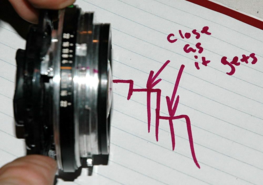
The goal is to have the optics as close to the camera sensor as possible to be able to focus as far away as possible. It is possible to assemble this so the plastic lens carrier bottoms out on the metal fine-thread helicoid and that helicoid bottoms on the lens chassis. This is as close as the optics can get to the camera without doing something even more drastic.
During this process you may discover you can't get the focus ring to move sometimes. It is possible to align the helicoids so the focus ring has reduced or no travel.
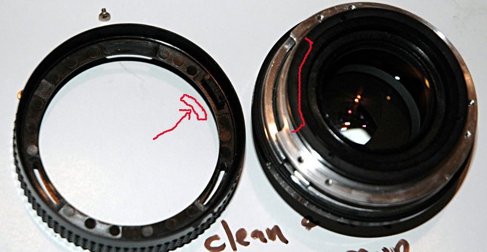
There is a cut-out in the metal helicoid (red crescent) and a cut-out on the metal frame beneath it. These line up when the lens is properly assembled. There is a tab protruding from the bottom of the focus ring (red rectangle). This pokes down into the gaps in the metal rings, and the tab hitting the ends of the gaps is what stops the focus ring moving at either end of the focus adjustment range. When the helicoids are not lined up right, the focus ring will have little or no travel, or it may just not fit on the lens at all.
Clean off the goop while you are in there. Just wipe with a clean cotton rag. My lens had quite a bit of excess grease inside.
I reassembled and "focused" the lens by hand to infinity. At this point, the lens was able to focus into the next room. Recall that, previously, it could only focus out to a couple of feet. This was progress. I noted the mirror hitting the rear element but it was not so surprising - there was no mount on the lens, so it was several millimeters farther into the camera than it would be when I was done. Also, I was hand-holding this very gently, so the lens was actually kicked out of the camera by the (weak) swinging mirror. At this point I started thinking there MAY be a problem with the protruding rear element vs. the camera's mirror.
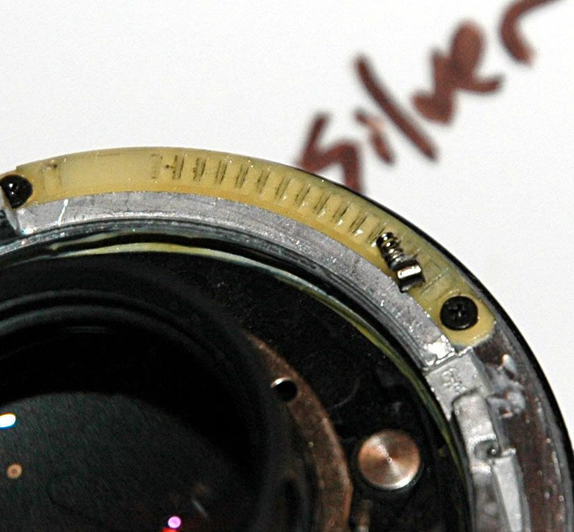
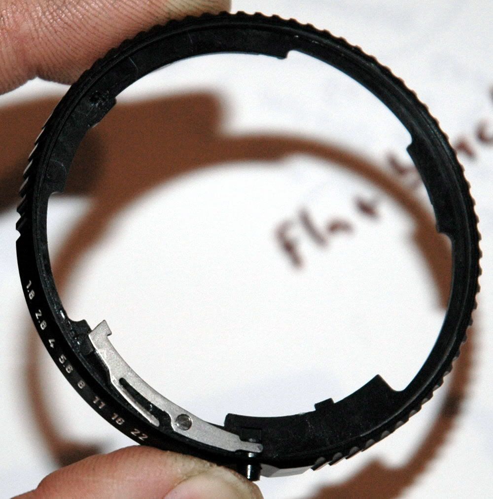
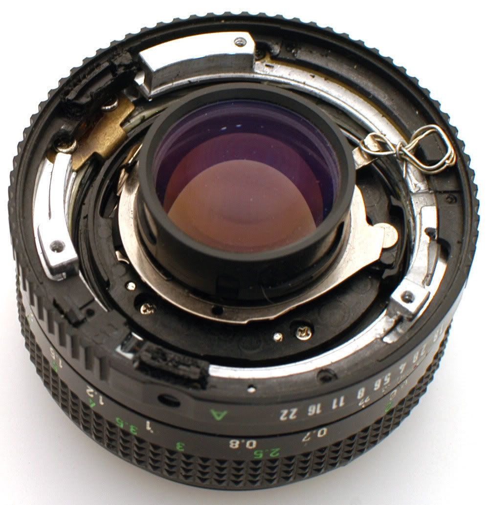
The aperture opening is set by the silver ring surrounding the lens.
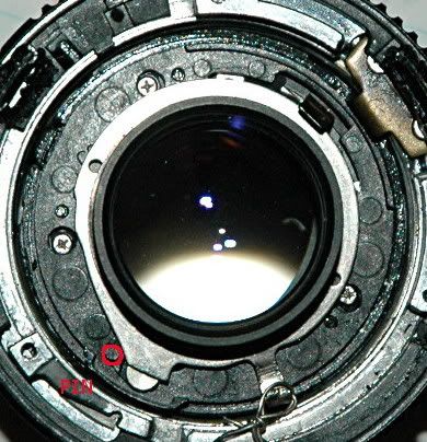
This ring has an angle (from 7:00 to 9:00 in this picture) that is ridden by a pin inside the iris mechanism. The farther away from the middle the pin gets, the wider the opening. Here the pin is almost to the farthest-away point on the angle, and the iris is pretty wide open.
There is a lever on this ring, to set the aperture opening. Remember the mechanism we took off the back of the lens right at the first, that was too wide to fit inside the F mount?
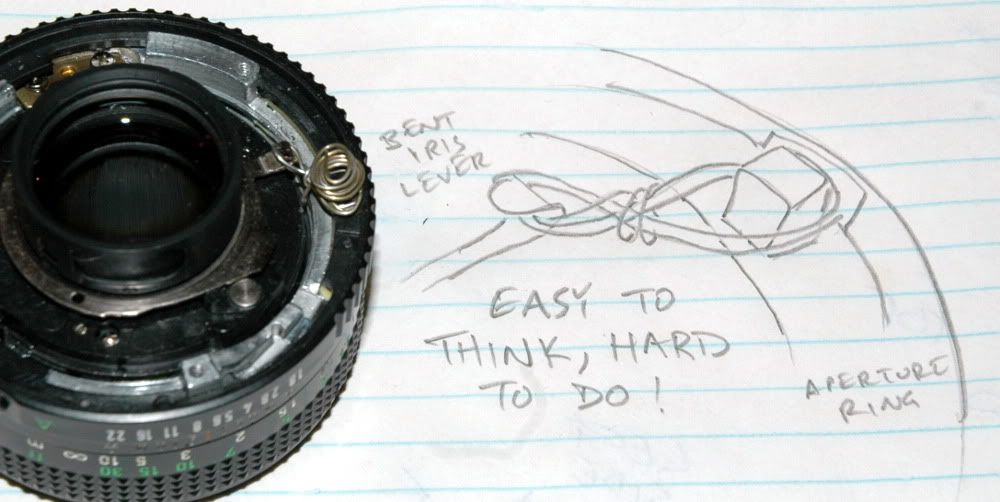
It had a lever that connected to the aperture ring lever. That was how the camera communicated to the lens what to do with the aperture when a photo was made. But Nikons stop down the wrong way, and that too-big ring mechanism is now gone. This leaves the aperture lever protruding too far (it would hit the F mount) and doing nothing. I bent the lever into a hook. I got the distinct impression that this lever wanted to break, so I went VERY gently with my needlenose pliers.
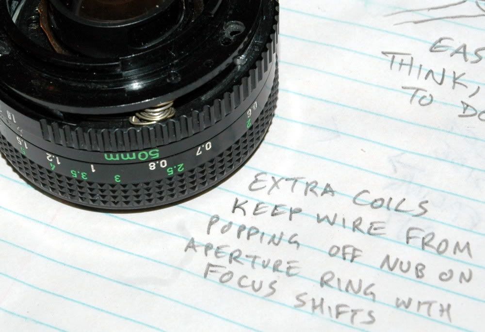
The f/ stop clicker has a housing on the aperture ring. That housing is a protrusion on the rear of the ring, and close to the iris lever when the lens is assembled, but they do not touch. I got some safety wire and bent it into a bracket to couple the aperture ring lever directly to the aperture ring. This was a bit tricky, but I got it done. Now rotating the aperture ring moves the iris lever, actuating the iris.
The little metal lever attached to the button protruding through the side of the lens had several purposes. One of those was retaining the aperture ring near the lens chassis. Without that lever, the aperture ring wants to pop loose at wide aperture settings. Nothing much but the f/clicker housing holds the aperture ring in place with this conversion halfway completed. My first attempt at having the aperture ring not pop out of position was mostly accomplished by using too many coils of wire on this "bracket" and it worked . . . sorta.
At this point, it looked like I would be able to try to fit the F mount. The stop-down lever (used by the camera to stop the iris closed to take a photo) is just a little bit too tall to fit inside this mount, so I carefully bent it in toward the optics just a little bit.
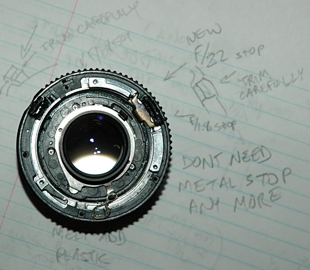
The mounting ring you pulled off the lens has a perfect set of holes for you to transfer to your F mount.
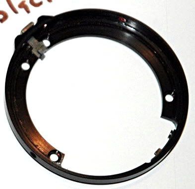
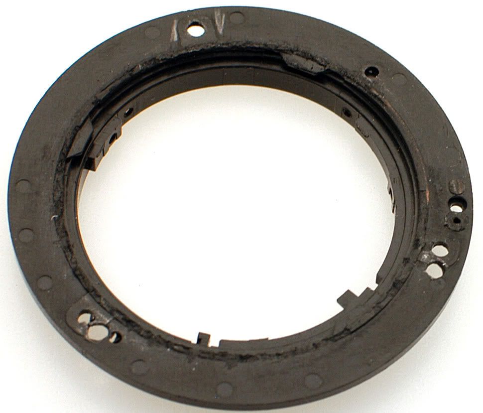
First you may need to modify your mount. I ordered a replacement part for the ubiquitous 18-55mm Nikkor "kit" lens, as it was
$10 on eBay. It had a bunch of stuff protruding on the inside which I removed with cutting pliers. You could also get a metal mount, from another lens. This was in part a proof-of-concept exercise so I went cheap.
There is a pin poking out of your camera. There is a recess on the back of your lenses at 9:00. The pin holds the lenses against rotation in the mount. Make 100% certain that you know which way is "up" when you take the next step! This means make sure you also know which way is "up" for the Canon lens. I chose to put the scales on top and have the orange line be the "top" of the lens.
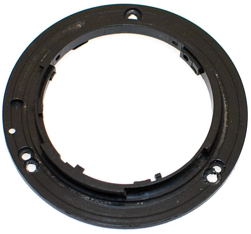
Place your trimmed-nearly-flat mount on your recently-removed "template" ring, and center it up very carefully. Triple-check everything to be sure it is oriented properly, centered, and all lined up. Transfer the holes with a marker, scribe, pencil, or whatever. Drill the screw holes. Then use a larger drill (I used a drill with a pilot tip) to cut the recesses in the back of the mount (the side which touches the camera) where the screw heads will sit. You want the screw heads to sit flush with the back of the mount. If they protrude they will wear on your camera's body mount flange (verrrr bad!) You need to drill two new holes and elongate one hole. This is what I ended up with:
The aperture ring installs on the lens chassis at a "wide open" setting. This means it wants to fall off at a wide open setting. Adjusting the iris required great care at this point, which sucked. I wanted to make a lens I could use without being careful not to break it. Recall that the aperture ring is held on only by the lens mount when the iris is wide open (there are some groove/slot deals that hold it together when the aperture is stopped-down).
At 10:00 and 2:00 in this picture, you can see where I fixed this. The f/clicker housing holds one third of the ring in position. I took a low powered soldering iron with a fine tip and some black plastic I had laying about, and "stung" the plastic to melt it to the aperture ring in two carefully-chosen spots. Choose the wrong spots and you can lose travel on the ring or even prevent it mounting on the lens! Use these spots I chose and you will reinforce the stops at each end of the adjustment range. After building up this new plastic, I trimmed it carefully until it was just small enough to fit the f/mount. This is easy to say, but somewhat tricky to do and easy to screw up if you don't have a gentle touch.
 So now:
- The aperture is controlled with the aperture ring
- The aperture ring will not fall off
- The focus ring will get the optics as far into the camera as possible
- The mount is drilled and trimmed to fit the lens
- It looks as if we're ready to go!
N.B.: The optics on this lens
absolutely will not support infinity focus on a nikon camera without shaving the mirror.
When I got the lens back together and went to make some pictures, there was a huge bummer that turned out to be not so huge: The mirror was hitting the rear lens element and getting hung up (leaving a dark viewfinder after taking a shot). Focusing just a hair closer (moving the optics away from the camera) released the mirror.
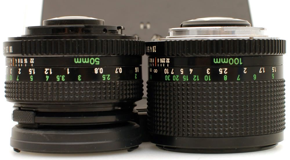
The rear lens element is held on with a plastic retaining ring. The ring just snaps on there, very easy to get on. It is a little tougher to pry off, but doable with a tiny flat head (jewelers) screwdriver. Here is a comparison to the 100mm lens I
also converted.
With rear lens retainer
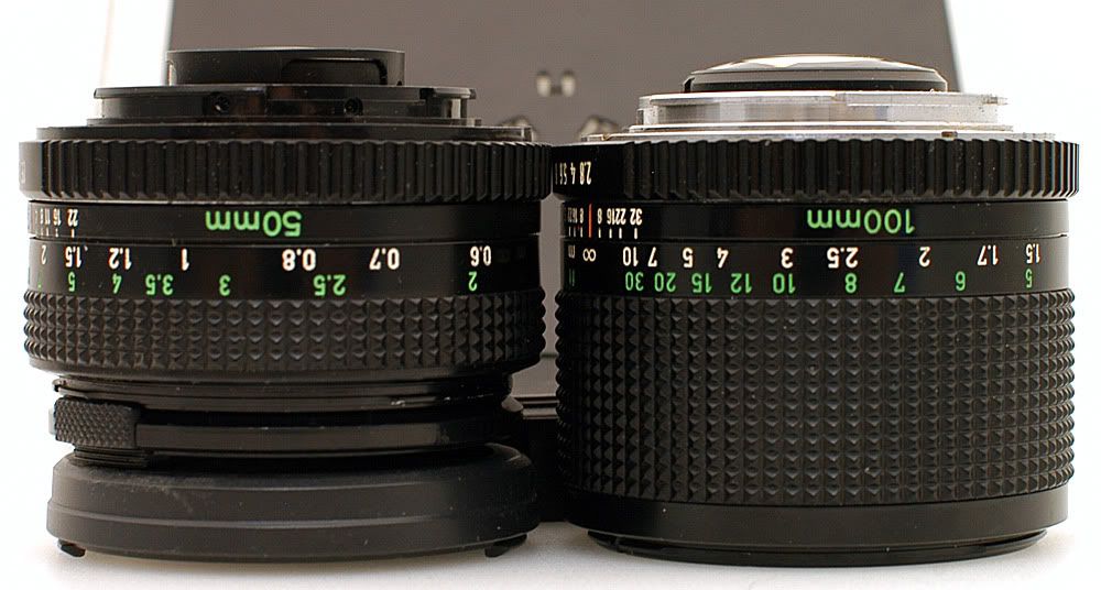
Without retainer
It seems like it would be great to just leave this retaining ring off, right? The problem is that the rear lens falls out. If I could be 100% sure it was perfectly clean inside, and that the glue wouldn't jack up the optics, I would glue this lens in place. I'm sticking with the retainer for now. That means shaving
something and it dang sure won't be my camera's mirror. I shaved this much off one side of the rear lens retainer with a super sharp knife. Be careful, because this retainer is thin, flimsy plastic. The corner of the lens pokes out now, but the mirror doesn't hit anymore. Notice that this shaved section of the retainer lines up on TOP of the lens. That is, it is on the same side as the orange line on "top" of the lens. The mirror was swinging UP and getting stuck on this retainer on TOP of the rear lens element.
After I was 100% done with this project, it seemed like I might be able to move the lenses
juuuuust a hair farther into the camera. I broke out the sandpaper. I sanded the front (lens side) of the F mount absolutely flat, and touched the back of the three mounting points where the lens and mount mate as well. I brought the optics in closer to the camera until the mirror started hanging on the rear lens again. It was still only focused "halfway across the street." I added some shims in between the mount and the lens and pushed the lens out another .2mm, and the mirror was free to swing again . . .
without infinity focus. You
must shave the mirror to achieve infinity focus with this lens on DX bodies, and full frame (35mm/FX digital) will need a positive trimming of the mirror. Remember that a proper Nikon Nikkor 50mm f/1.8 lens is only $100 before you start thinking of shaving that mirror!
Assembly is the reverse of disassembly. If you can't figure out how to assemble this lens by now,
please don't screw it up and try the conversion on your own. Talk to someone who knows how to do it, or just let them do it.
Put it all together again.
Lens Porn: CANON LENS FD 50mm 1:1.8 CANON LENS MADE IN JAPAN . . . in Nikon F mount
Mounted on my workhorse:
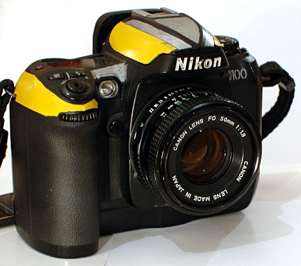
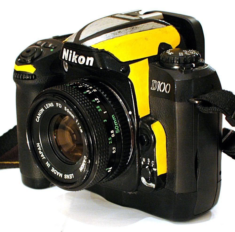
Awwww,
it's tiny!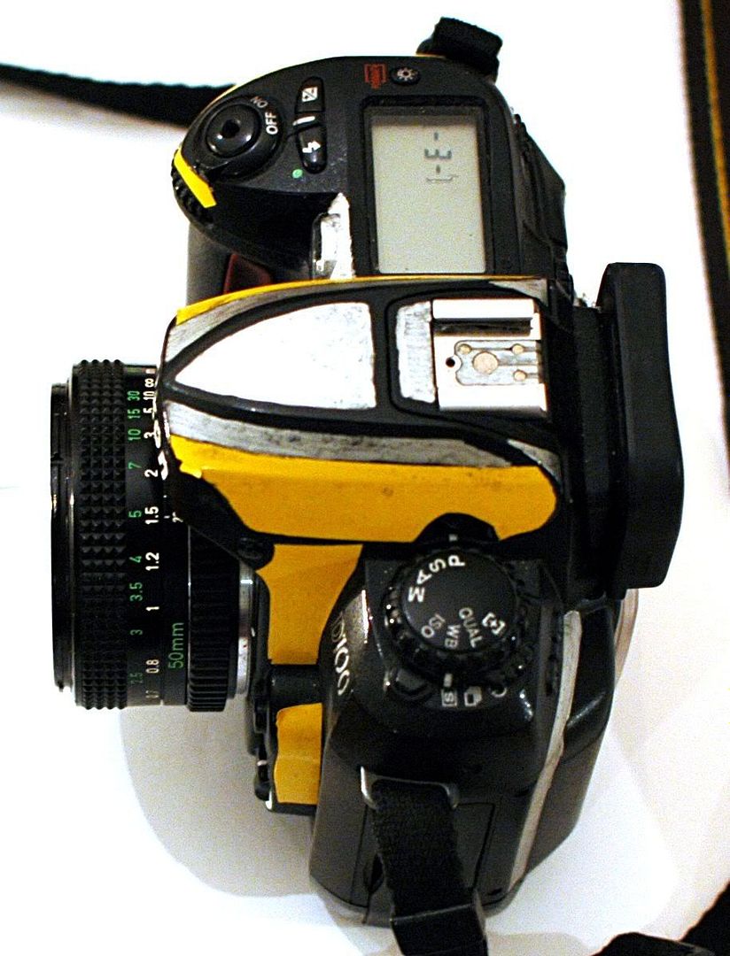
So, does it work? Let's ask it!
(this picture was reversed to alleviate reader confusion. The camera took a picture of this lens, through this lens, looking into a mirror. This image is backwards!)Note: I did
nothing to the color in any of the shots taken with this camera*. I just resized them. The exposures you see are what it shot, straight off the sensor. I did not sharpen any of these sample shots, either . . . this lens is just that sharp.
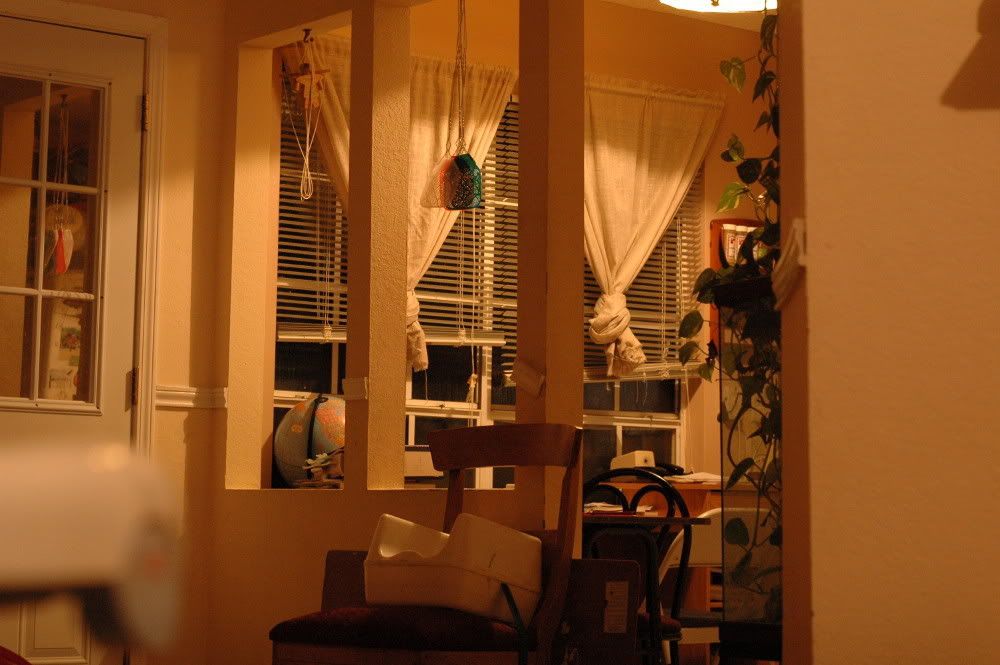
The colored blobs are refrigerator magnets. The blinds are closed, and the sun is still on the way up. The light, it was dim! This was f/1.8 @ 1/30 second.

Sharp? Yes, we have them.

I took a trip to the local rose garden (a.k.a. the back yard) for the sheer joy of making beautiful photographs with my "new" lens.
Here we have a shot with a wide aperture at 1/125

and a narrow aperture with flash at the same 1/125.

Same type of deal: wide open at 1/200

And stopped down using the onboard speedlight at 1/500

A note on Bokeh: This lens is okay. You see some CA and a bit of flare in the first shot, above, because it was looking into a noon sky through big gaps in the overhead tree leaves. These are greatly reduced with the different exposure in the next shot.
There is a picket fence in the background, almost totally blurred-out. Where is that Like button?

Better yet, a plain dirt-and-rocks background looking like a gray sheet

So this is wonderful.
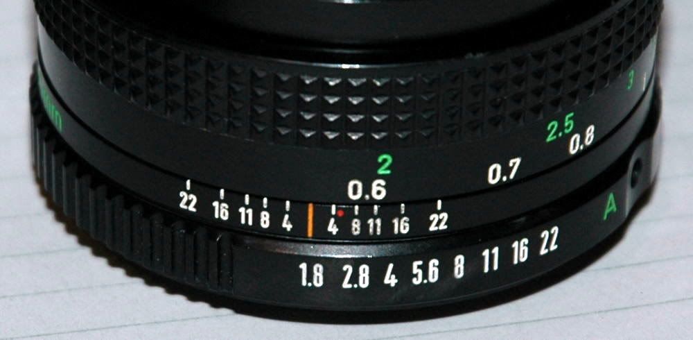
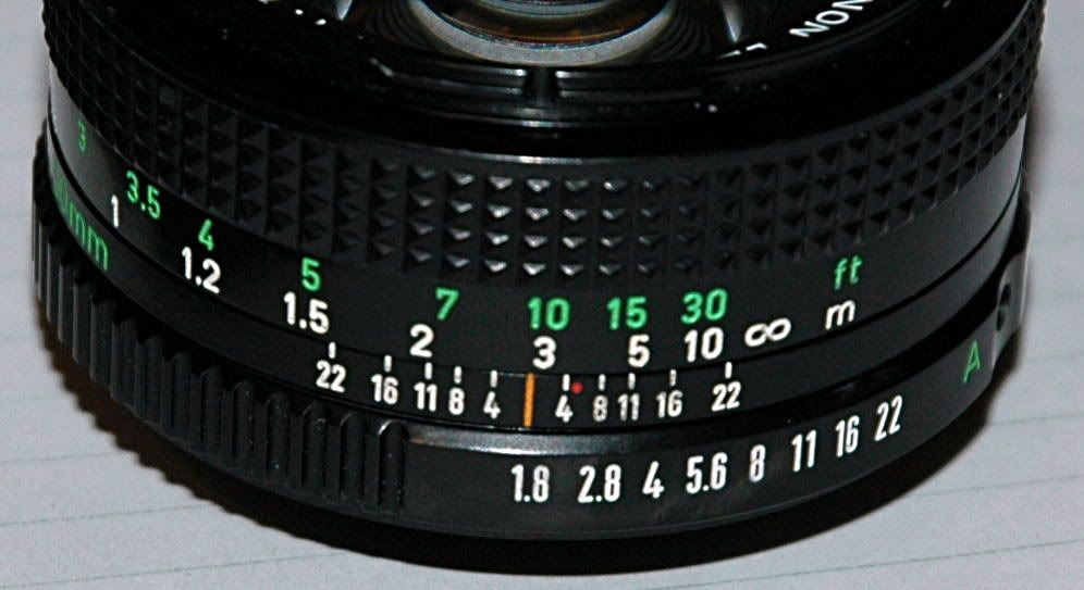
This lens focuses down to a couple of feet. Unfortunately, the distance scales are WAY off. At one point I did get the helicoids lined up so the distance scales made sense, but then the focus was off. I'll take focus over working scales, so the following are what is showing on the scales at minimum and maximum focus ditances. This is something with which I can live, trusting my eye to set the focus. I suppose I could paint on my own distance scale, but who wants to put
work into a camera lens!? :-)
More-unfortunately, all I could get out of this lens for distant focus is "all the way across the living room" which is the same as "just shy o' halfway across the street from my driveway" (a quick test with flash, handheld at 1/25 second)
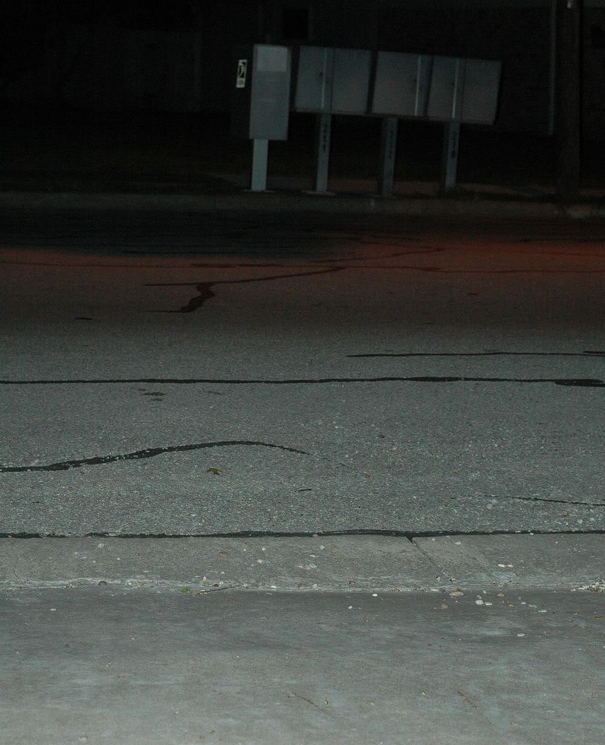
Stopping
way down and using a 15-second exposure (camera sitting on top of my car) got me usable focus clear across the street. I was afraid that the truck which drove through my midnight photo shoot would throw off the exposure, but it just left a few streaks from its lights and roof as it drove through.
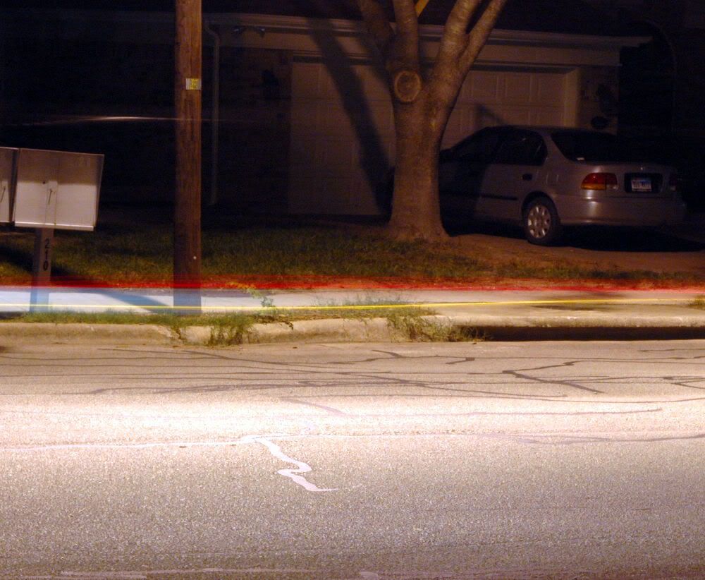 *except for this exposure, wich was crazy with the color from the street lamp and I didn't feel like taking more exposures just for a better white balance
A note on these exposure times: This is sweet. One of the reasons a D70 is great is that it will sync with its onboard flash all the way down to 1/500 second. With a dummy external speelight, you can get even crazier out to 1/8000. This is NOT standard fare. My D100 at work only syncs to 1/160 which is not always sufficient and makes getting black backgrounds at noon with a flash more of a challenge.
But I can, so allow me!


Vote For David disclaims any and all liability for damages incurred when you destroy your lens. If you don't think you can do this work, please stop and let someone else do it who can.


